CDE2310 Group 1 — AMR for Smart Warehouse Intralogistics
System documentation for the autonomous mobile robot (TurtleBot3 Burger) designed for smart warehouse intralogistics.
🔗 Navigation
- Home
- Requirements
- Con-Ops
- High Level Design
- Interface Control Documents
- Software Development ← You are here
- Testing
- User Manual
- Bill-Of-Materials
- Electrical Subsystem
- Mechanical Subsystem
- Improvements
Software/Firmware Development Documentation
1. Software Architecture Overview
The software system is built on ROS 2 Humble running on the Raspberry Pi 4B. It consists of a central mission controller FSM, a standalone ArUco detection pipeline, a hardware launcher controller, and the standard TurtleBot3/Nav2 stack components.
1.1 ROS 2 Packages
| Package | Description |
|---|---|
auto_nav |
Primary package containing the mission controller, exploration FSM, and launch files |
py_pubsub |
Utility package for basic ROS 2 publisher/subscriber testing |
testbed_pkg |
Testbed package for early assignment exercises |
turtlebot3_simulations |
Standard TurtleBot3 Gazebo simulation environment |
1.2 Node and Script Registry
| Executable / Script | Entry Point | Run Location | Purpose |
|---|---|---|---|
mission_controller |
auto_nav.exploration_fsm:main |
Laptop (via launch file) | Central mission FSM — orchestrates exploration, docking, and delivery |
mission_gui |
auto_nav.mission_gui:main |
Laptop (manual) | Tkinter-based GUI for real-time mission monitoring |
aruco_live.py |
Standalone script | RPi (via SSH) | Camera capture, ArUco detection, pose estimation, ROS 2 publishing |
ball_launcher.py |
Standalone script | RPi (via SSH) | ROS 2 services for flywheel and servo hardware control |
aruco_dock.py |
Standalone script | Laptop (manual) | Standalone docking test — Nav2 + cmd_vel approach to a single marker |
station_b_launcher.py |
Standalone script | Laptop (manual) | Standalone Station B fire sequence test (assumes already docked) |
system_test.py |
Standalone script | Laptop (manual) | Pre-flight integration test with Tkinter GUI |
bringup_all.launch.py |
Launch file | Laptop | Unified launch: Cartographer → Nav2 → Mission FSM (event-driven) |
2. Mission Controller (exploration_fsm.py)
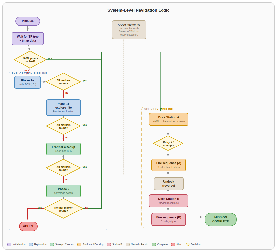 System-level navigation logic showing the full mission FSM from initialisation through exploration, docking, and delivery.
2.1 Finite State Machine
The UltimateMissionController is a single ROS 2 node that acts as the orchestrator for the entire mission. It manages high-level phase transitions and coordinates between all subsystems. The FSM follows this sequence:
- Initialisation — Wait for SLAM map and valid TF transforms.
- Phase 1a — Initial BFS coverage sweep (15 s budget).
- Phase 1b — Frontier exploration via explore_lite (up to 600 s).
- Phase 1c — Frontier cleanup BFS (short-hop, time-decaying blacklist).
- Phase 2 — Full coverage sweep (last resort, if markers still missing).
- Station A Docking & Delivery — Coarse-to-fine approach + timed fire sequence.
- Station B Docking & Delivery — Coarse-to-fine approach + trigger-based fire sequence.
- Mission Complete — Publish completion signal and log final state.
The controller exits early from exploration as soon as all required markers (Station A and B) are detected.
2.2 Key Configuration Parameters
| Parameter | Value | Description |
|---|---|---|
TARGET_DISTANCE |
0.10 m | Final dock distance from marker |
NAV2_APPROACH_DISTANCE |
0.35 m | Runway distance for live marker approach |
YAML_APPROACH_DISTANCE |
0.60 m | Coarse approach distance using stored pose |
MAX_DOCK_RETRIES |
3 | Maximum docking attempts per station |
UNDOCK_DISTANCE |
0.30 m | Reverse distance after Station A delivery |
STATION_A_FIRE_DELAYS |
[6.0, 9.0, 1.0] | Team-specific timing delays (seconds before each ball) |
STATION_B_BALLS |
3 | Number of balls to fire at Station B |
TRIGGER_COOLDOWN |
5.0 s | Wait after firing for trigger marker to clear |
EXPLORATION_TIMEOUT |
600 s | Maximum time for explore_lite |
INITIAL_BFS_DURATION |
15 s | Time budget for initial BFS sweep |
FRONTIER_BLACKLIST_TTL |
90 s | Time-decaying blacklist entry lifetime |
FRONTIER_BLACKLIST_RADIUS |
0.30 m | Exclusion radius around failed frontier goals |
FRONTIER_HOP_DISTANCE |
0.60 m | Maximum travel per frontier cleanup hop |
2.3 Visual Servo Control Parameters
| Parameter | Value | Description |
|---|---|---|
K_LINEAR |
0.3 m/s per m | Proportional gain for forward velocity |
K_ANGULAR |
1.5 rad/s per m | Proportional gain for angular correction |
MAX_LINEAR |
0.08 m/s | Maximum forward speed during approach |
MAX_ANGULAR |
0.50 rad/s | Maximum angular speed during alignment |
ALIGN_TOL_A |
0.03 m | Lateral tolerance for Station A |
ALIGN_TOL_B |
0.01 m | Lateral tolerance for Station B (tighter for moving target) |
BLIND_THRESHOLD |
0.20 m | cam_z below which camera detection is unreliable |
LOST_MARKER_S |
3.0 s | Tolerated gap before declaring marker lost |
3. Exploration Strategy
3.1 Multi-Layered Pipeline
| Stage | Strategy | Purpose |
|---|---|---|
| Phase 1a | Timed BFS Coverage Sweep | Rapid initial map seeding across known free space (15 s budget) |
| Phase 1b | explore_lite (frontier-based) | Systematic frontier exploration with up to 600 s timeout |
| Phase 1c | Frontier Cleanup (short-hop BFS) | Targeted cleanup of remaining frontiers that explore_lite missed |
| Phase 2 | Full Coverage Sweep | Exhaustive BFS visit of every reachable free cell as last resort |
3.2 Frontier Cleanup Algorithm (Phase 1c)
- BFS from the robot’s current position across free cells to find the nearest frontier.
- Trace the BFS parent chain to get a path through known free space.
- Navigate along this path in short hops (0.6 m increments).
- After each hop, the map has updated from new LiDAR scans; BFS is recomputed.
Robustness features: time-decaying blacklist (TTL = 90 s, radius = 0.30 m) prevents oscillation; costmap clearance checking (0.22 m) ensures navigable targets; recovery spins (360°) trigger after 3 consecutive failures; frontier clustering groups connected cells and snaps goals to reachable centroids.
4. SLAM and Navigation
4.1 Cartographer SLAM
Google Cartographer fuses three data sources for real-time SLAM:
| Source | Purpose |
|---|---|
| LDS-02 LiDAR | 360° range measurements for scan matching and map construction |
| Wheel Encoders | Odometry estimates for inter-scan motion prediction |
| IMU | Inertial data for orientation refinement and drift correction |
Map output: occupancy grid at 0.05 m/cell resolution — free (0), occupied (100), unknown (-1) — published on /map.
4.2 Nav2 Stack Configuration
| Component | Selection | Role |
|---|---|---|
| Global Planner | NavFn (A*) | Shortest collision-free path through global costmap |
| Local Controller | DWB (Dynamic Window Approach) | Real-time velocity commands for obstacle avoidance |
| Costmap | Global + Local layers | Inflated obstacle layers for safe path planning |
| Recovery Behaviors | Spin, BackUp, Wait | Automated recovery when the robot gets stuck |
Key burger.yaml parameters: xy_goal_tolerance: 0.25, controller_frequency: 10.0 Hz, robot_radius: 0.17 m (local) / 0.1 m (global), inflation_radius: 0.25 m, cost_scaling_factor: 1.5.
4.3 Algorithm Selection Rationale
Cartographer over SLAM Toolbox: Superior map quality critical for docking alignment; higher CPU load acceptable on RPi 4B.
DWB over MPPI: Proven reliability in indoor corridors with lower computational overhead; response latency consistently under 100 ms. MPPI offers smoother trajectories in open spaces but adds unnecessary complexity for structured maze corridors.
5. ArUco Detection Pipeline (aruco_live.py)
5.1 Pipeline Stages
- Capture — Frames at 640×480 resolution, 30 FPS via V4L2.
- Preprocessing — Grayscale conversion for improved bit-pattern recognition.
- Detection —
cv2.aruco.ArucoDetectorwithDICT_6X6_250identifies marker boundaries. - Pose Estimation —
cv2.solvePnPwithSOLVEPNP_IPPE_SQUAREextracts rotation vector (rvec) and translation vector (tvec) from the marker’s four corner points and the camera calibration matrix (loaded from.npzfile). - Quaternion Conversion — rvec → rotation matrix via
cv2.Rodrigues→ unit quaternion (x, y, z, w) using Shepperd trace method. - ROS 2 Publishing — Detected markers published on
/aruco/markersasvisualization_msgs/MarkerArray.
5.2 Camera Calibration
Camera intrinsic matrix (K) and distortion coefficients are loaded from /home/ubuntu/calibration.npz. The marker object points are defined as a 4-point square at the physical marker size (5 cm default).
5.3 Camera-to-Map Coordinate Transform
When the mission controller receives a marker, it transforms camera-frame coordinates to map-frame:
- Look up
map → base_linkTF to get robot pose and yaw. - Apply camera X offset (4 cm lateral) and project camera-frame point into map frame.
- Extract marker outward normal direction from orientation quaternion (defines docking approach heading).
- Store as
(map_x, map_y, normal_yaw)in detected markers dictionary.
6. Docking Logic
6.1 Coarse-to-Fine Approach
Stage 1 — Coarse Nav2 Approach: Navigate to standoff point 0.6 m from stored marker position along its normal direction using Nav2 global planner.
Stage 2 — Live Marker Acquisition: Wait for fresh camera sighting (360° spin search if not visible). Update pose to correct SLAM drift. New Nav2 goal at 0.35 m from live position.
| Stage 3 — Visual Servo (cmd_vel): Three sub-phases — Align (rotate until | cam_x | < tolerance), Drive (forward + angular correction until blind threshold), Dead-reckon (fixed speed through camera blind zone to reach 0.10 m target). |
6.2 Station A — Timed Fire Sequence
- Flywheel spin-up via
/start_flywheel. - Wait 6.0 s → fire ball 1 via
/fire_ball. - Wait 9.0 s → fire ball 2.
- Wait 1.0 s → fire ball 3.
- Flywheel stop via
/stop_flywheel. - Undock — reverse 0.30 m at 0.06 m/s.
6.3 Station B — Trigger-Based Fire Sequence
- Dock with 1 cm lateral tolerance.
- Flywheel spin-up.
- Wait for trigger marker (ArUco ID 2) detection → fire ball.
- Cooldown 5.0 s (prevent double-fire on same receptacle pass).
- Repeat for 3 balls total (30 s timeout per ball).
- Flywheel stop.
7. Launcher Hardware Controller (ball_launcher.py)
Runs on the RPi as a ROS 2 node exposing three services:
| Service | Behaviour |
|---|---|
/start_flywheel |
Sets both Motor A and Motor B to forward(1.0) via gpiozero.Motor |
/fire_ball |
Triggers servo actuation (placeholder — servo implementation pending) |
/stop_flywheel |
Calls stop() on both motors |
GPIO configuration: Motor A (fwd=23, bwd=24, en=13), Motor B (fwd=22, bwd=27, en=12). Graceful degradation to simulation mode if gpiozero is not available.
8. Source Code Structure
├── docs/                              # Documentation markdown files
│   ├── challenge.md                   # Problem definition and requirements
│   ├── general-system.md              # System architecture overview
│   ├── software.md                    # Software subsystem documentation
│   ├── docking.md                     # Docking & delivery subsystem
│   ├── improvements.md                # Areas for improvement
│   └── assets/                        # Diagrams and images
├── software/
│   ├── Navigation/Params/burger.yaml  # Nav2 parameter configuration
│   ├── docking/
│   │   ├── local/
│   │   │   ├── aruco_dock.py          # Standalone docking test (laptop)
│   │   │   ├── aruco_dock_and_launch_test.py
│   │   │   ├── aruco_dock_moving.py   # Moving target docking test
│   │   │   └── station_b_launcher.py  # Standalone Station B fire test
│   │   └── rpi/
│   │       ├── aruco_live.py          # ArUco detection (runs on RPi)
│   │       └── ball_launcher.py       # Hardware launcher controller (RPi)
│   └── system_test.py                # Pre-flight integration test with GUI
├── src/
│   ├── auto_nav/                      # Primary ROS 2 package
│   │   ├── auto_nav/
│   │   │   ├── exploration_fsm.py     # Mission controller FSM (1368 lines)
│   │   │   ├── mission_gui.py         # Tkinter mission monitoring GUI
│   │   │   ├── r2auto_nav.py          # Earlier navigation prototype
│   │   │   ├── r2mover.py             # Basic movement node
│   │   │   ├── r2moverotate.py        # Move and rotate node
│   │   │   ├── r2occupancy.py         # Occupancy grid utilities
│   │   │   ├── r2occupancy2.py        # Occupancy grid utilities v2
│   │   │   └── r2scanner.py           # LiDAR scanner utilities
│   │   ├── launch/
│   │   │   └── bringup_all.launch.py  # Unified launch file
│   │   ├── package.xml
│   │   └── setup.py
│   ├── py_pubsub/                     # Basic pub/sub test package
│   ├── testbed_pkg/                   # Assignment testbed package
│   └── turtlebot3_simulations/        # Standard TurtleBot3 simulation
├── Electrical/                        # Electrical subsystem documentation
│   ├── Electrical.md
│   └── assets/images/                 # Circuit and architecture diagrams
└── Mechanical/
    └── CAD Files/                     # SolidWorks parts and assemblies
9. Build and Deployment
9.1 Build Commands
# Install dependencies
rosdep install --from-paths src --ignore-src -r -y

# Build workspace
colcon build --symlink-install

# Source the workspace
source install/setup.bash
9.2 Deployment Sequence
- Power on TurtleBot3.
- SSH into Raspberry Pi.
- On RPi:
python3 main_launch.py(starts aruco_live.py and ball_launcher.py). - On laptop:
ros2 run auto_nav mission_gui(start monitoring GUI). - On laptop:
ros2 launch auto_nav bringup_all.launch.py(start mission). - Monitor via RViz and mission GUI.
9.3 Parameter Tuning
After modifying burger.yaml or mission controller parameters, rebuild:
colcon build --packages-select auto_nav
source install/setup.bash
10. Visualization and Debugging
10.1 RViz Monitoring
- Live occupancy grid map from Cartographer
- Robot pose and TF tree
- Nav2 planned paths and costmaps
- ArUco marker detections
10.2 Mission Phase Logging
The controller publishes the current mission phase on /mission_phase as a String topic. Phase transitions are logged to the ROS 2 logger. At Station B, additional diagnostics track trigger detection count and balls fired.
10.3 Safety Mechanisms
- Immediate Nav2 goal cancellation when all markers found during exploration.
- Flywheel activation only after confirmed docking; always stopped via service call after firing.
- Marker loss handling: abort approach if marker lost > 3 seconds.
- Mission abort if no markers found after all exploration strategies.
- Post-delivery undock to prevent blocking the receptacle.