CDE2310 Group 1 — AMR for Smart Warehouse Intralogistics
System documentation for the autonomous mobile robot (TurtleBot3 Burger) designed for smart warehouse intralogistics.
🔗 Navigation
- Home
- Requirements
- Con-Ops ← You are here
- High Level Design
- Interface Control Documents
- Software Development
- Testing
- User Manual
- Bill-Of-Materials
- Electrical Subsystem
- Mechanical Subsystem
- Improvements
Concept of Operations (Con-Ops)
Operational Environment
The robot operates in an unknown indoor warehouse maze environment constructed from physical walls and barriers. The maze layout is unknown prior to mission start and may include narrow corridors, dead ends, and occluded regions. Two delivery stations (Station A and Station B) are positioned within the maze at unknown locations, each marked with ArUco markers. An optional elevator provides access to a second level for a bonus delivery objective.
Lighting conditions may vary across the warehouse. The floor surface is flat and suitable for differential-drive wheeled locomotion. No dynamic obstacles (personnel) are expected during the mission window, though the system is designed with obstacle avoidance as a core capability.
Stakeholders and Actors
| Actor | Role |
|---|---|
| Operator | Places the robot at the start zone, powers it on, initiates the mission via launch file, and monitors progress via RViz and the mission GUI. No physical intervention permitted after start declaration. |
| Robot (AMR) | Autonomously explores the maze, detects stations, docks, and delivers ping pong balls. |
| Station A | Fixed receptacle — receives 3 balls in a team-specific timed sequence. |
| Station B | Oscillating receptacle on a motorised rail — receives 3 balls via trigger-based firing synchronised to the receptacle’s motion. |
| Station C (Bonus) | Level 2 delivery station — accessed via elevator traversal using REST API calls. |
Mission Phases
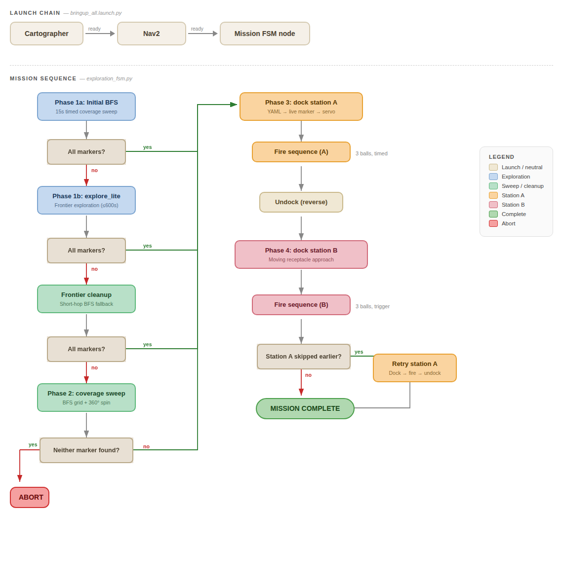 End-to-end mission flow from boot to mission completion.
The mission follows a sequential pipeline with built-in fallback layers at each stage. The total mission window is 25 minutes, including setup and cleanup.
Phase 1 — Setup & Boot
The operator places the robot at the designated start zone and powers it on. A single ROS 2 launch file (bringup_all.launch.py) initialises all nodes in dependency order:
- Cartographer starts immediately and begins SLAM from LiDAR and IMU data.
- Nav2 starts when Cartographer signals readiness (map creation detected).
- Mission FSM Node (
UltimateMissionController) launches when Nav2 signals readiness.
The aruco_live.py script is started separately on the RPi via SSH to begin camera-based marker detection. The system waits for a valid map and robot localisation before proceeding to exploration.
Phase 2 — Autonomous Exploration
The robot explores the unknown maze using a multi-layered pipeline designed to ensure all station markers are found:
Stage 1a — Initial BFS Sweep (15 s): A quick BFS coverage sweep across known free space seeds the map and may detect markers before the heavier frontier explorer launches.
Stage 1b — Frontier Exploration (explore_lite, up to 600 s): The primary exploration phase uses frontier-based exploration to systematically target boundaries between known and unknown space, publishing Nav2 goals to drive the robot toward unmapped regions.
Stage 1c — Frontier Cleanup: If explore_lite completes but required markers are still missing, an in-process BFS frontier cleanup targets small unexplored pockets using short hops with time-decaying blacklisting and recovery spins.
Stage 2 — Full Coverage Sweep (last resort): If markers remain undetected after all frontier strategies, a full BFS sweep visits every reachable free cell.
Throughout exploration, the ArUco detection script runs continuously. Any marker sighted is immediately published to ROS 2, transformed to map-frame coordinates, and persisted to YAML for later docking.
Phase 3 — Station A: Static Delivery
Once Station A’s marker (ArUco ID 0) has been detected, the robot navigates to the station using a coarse-to-fine docking strategy:
- Coarse Nav2 Approach — Navigate to a standoff point 0.6 m from the stored marker position using Nav2’s global planner for collision-free routing.
- Live Marker Refinement — Acquire a fresh camera sighting to correct for SLAM drift, setting a new Nav2 goal at 0.35 m from the live marker position.
- Visual Servo Approach — Final precision approach using direct
cmd_velcommands with proportional control (align → drive → dead-reckon through the camera blind zone below 0.20 m) to reach the 0.10 m target docking distance.
Upon successful docking, the robot executes a timed firing sequence: flywheel spin-up, then 3 balls fired with team-specific delays of [6.0 s, 9.0 s, 1.0 s] between shots. After delivery, the robot reverses 0.30 m to clear the station.
Phase 4 — Station B: Dynamic Delivery
Station B (ArUco ID 1) follows the same coarse-to-fine docking pipeline but with tighter alignment tolerance (1 cm lateral vs 3 cm for Station A).
Firing is trigger-based rather than timed: a secondary ArUco marker (ID 2) inside the moving receptacle signals when the hole is aligned with the robot. Each ball is fired on trigger detection, with a 5.0-second cooldown between shots to prevent double-firing on the same pass. If no trigger is detected within 30 seconds, the sequence aborts.
Phase 5 — Mission Complete
After both stations have been serviced, the mission controller publishes a completion signal and logs the final state. The operator can review the mission timeline via the mission GUI and RViz.
Mission Phase Ordering Logic
The controller handles a common edge case where stations are detected in different orders:
- If Station A is detected during exploration, it is serviced first, then Station B.
- If only Station B was found initially, it is serviced first.
- After Station B, the system re-checks if Station A has since been detected (it may have been spotted during transit to Station B).
- If so, Station A docking and delivery is executed as a late retry.
This ensures both stations are always attempted regardless of discovery order.
Fault Tolerance and Recovery
| Fault | Recovery Strategy |
|---|---|
| Frontier explorer fails to find all markers | System automatically escalates through progressively more thorough search strategies (BFS sweep → frontier cleanup → full coverage sweep) |
| Marker not visible at stored location | 360° spin search performed before declaring failure |
| Docking alignment failure | Each station allows up to 3 retries with fresh marker acquisition between attempts |
| Marker lost during visual servo | Approach aborted if marker lost for > 3 seconds; switches to dead-reckoning if within blind zone |
| Mission attempt fails partway through | Detected marker poses are persisted to YAML; on re-attempt, the robot can skip exploration and proceed directly to docking |
| No station markers found after all strategies | Mission aborts cleanly rather than entering an undefined state |
Operational Timeline (Nominal)
| Phase | Estimated Duration | Cumulative |
|---|---|---|
| Setup & Boot | 1–2 min | 2 min |
| Exploration (Stages 1a–1c) | 5–12 min | 14 min |
| Station A Docking & Delivery | 2–4 min | 18 min |
| Transit to Station B | 1–2 min | 20 min |
| Station B Docking & Delivery | 2–4 min | 24 min |
| Mission Complete & Cleanup | 1 min | 25 min |
The 25-minute window includes setup, execution, and cleanup. Achievement objectives take precedence over timing — completing both stations slowly outscores completing one station quickly.
Monitoring and Observability
During operation, the following monitoring interfaces are available:
RViz — Displays the live occupancy grid map, robot pose and TF tree, Nav2 planned paths and costmaps, and ArUco marker detections.
Mission GUI (mission_gui) — Displays the current mission phase, marker detection status, docking attempt outcomes, and ball delivery logs.
Mission Phase Topic — The controller publishes the current phase on /mission_phase as a String topic, enabling real-time monitoring and post-analysis.
ROSBAG — Continuous recording of all relevant topics throughout the mission for post-mission review and performance analysis.