CDE2310 Group 1 — AMR for Smart Warehouse Intralogistics
System documentation for the autonomous mobile robot (TurtleBot3 Burger) designed for smart warehouse intralogistics.
🔗 Navigation
- Home
- Requirements
- Con-Ops
- High Level Design
- Interface Control Documents
- Software Development
- Testing
- User Manual
- Bill-Of-Materials
- Electrical Subsystem
- Mechanical Subsystem ← You are here
- Improvements
Mechanical Subsystem Documentation
This document outlines the design, iteration, and assembly of the custom payload for the TurtleBot, detailing how we achieved a compact, reliable, and precise ping pong ball launching system.
1. System Overview
The mechanical subsystem is designed to securely transport and fire ping pong balls into a docking receptacle. The system consists of:
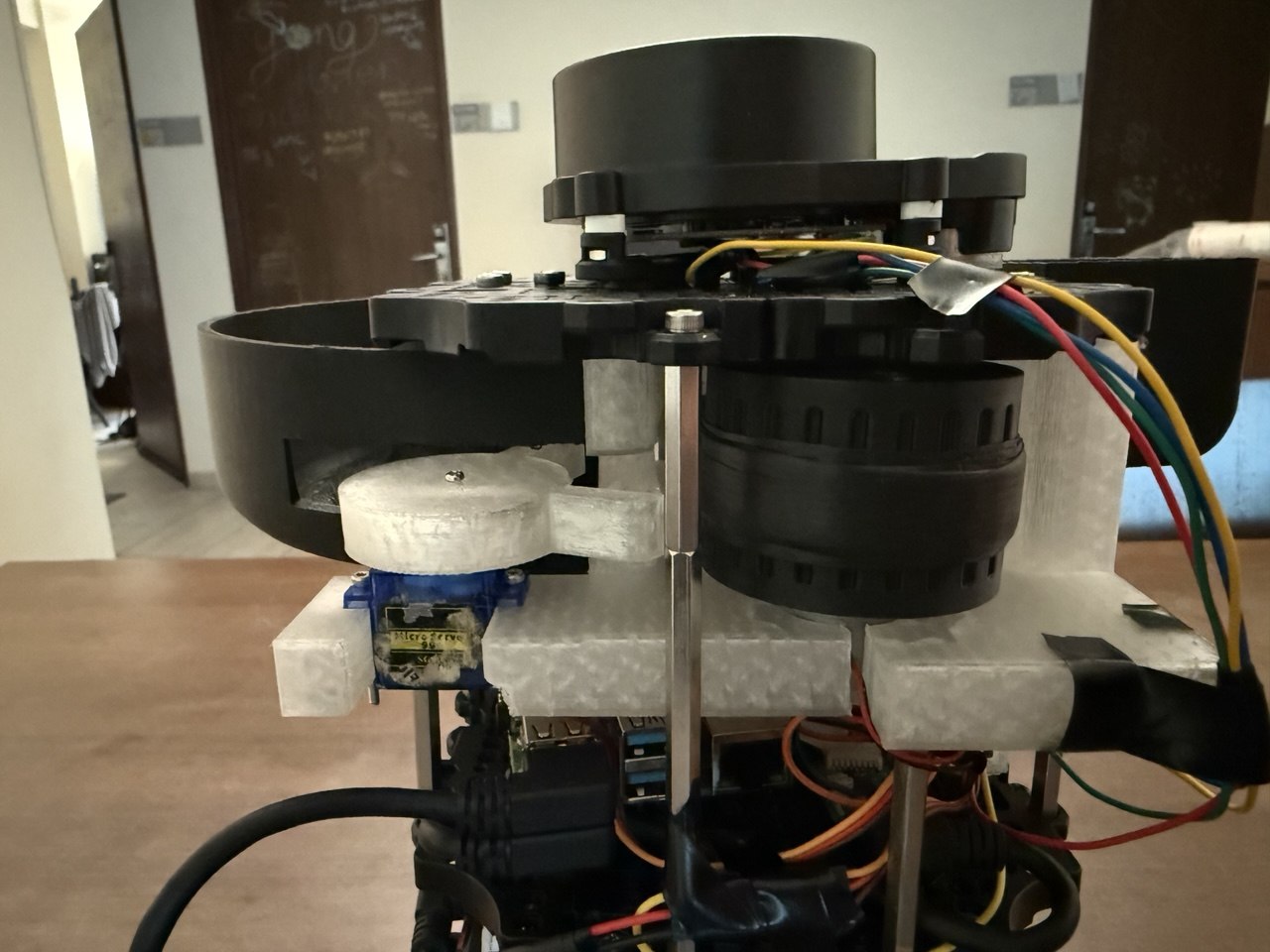
- A compact, internally mounted launching mechanism that securely holds the flywheel and feeder in between the robot’s structural layers.
- A gravity-assisted, servo-controlled feeder with a rotating arm for precise, single-ball release.
- A dual-flywheel launcher integrated directly into the robot’s internal structural layers to ensure a straight, spin-free launch.
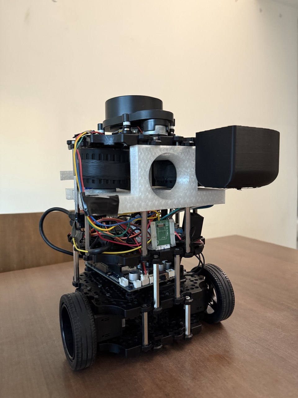
- A low-profile design that maintains the LiDAR sensor unobstructed by any components
Physical Specifications
| Parameter | Value |
|---|---|
| Total Mass | 1402.24 g (1.40 kg) |
| Overall Dimensions (L × W × H) | 138 mm × 178 mm × 192 mm |
| Centre of Gravity — X (back +) | −56.7 mm from ball-caster origin |
| Centre of Gravity — Y (up) | 95.3 mm from ground |
| Centre of Gravity — Z (left +) | 2.8 mm from ball-caster origin |
Design Constraints
- All mounted components must not obstruct the LDS-02 LiDAR’s 360° field of view.
- The ball storage tube follows a curved path to stay below the LiDAR plane while maintaining gravity-feed functionality.
- The centre of gravity must remain low for stable navigation; the mounted payload must not shift during transit.
- The robot must be compact enough to navigate narrow maze corridors without wall contact.
2. Problem Description & Design Requirements
To successfully complete the docking and firing tasks, the mechanical subsystem had to satisfy several strict constraints:
- Payload Capacity: Store exactly nine 2.7g ping pong balls securely without them escaping during movement or navigation
- Dimensional Constraints: Maintain a narrow overall footprint to ensure the robot can navigate tight maze environments without collision.
- Sensor Clearance: Ensure zero obstruction to the 360° field of view of the LDS-02 LiDAR without requiring external sensor mounts or height modifications.
- Launch Kinematics: Fire balls horizontally across a 15–25 cm docking gap with minimal vertical drop, ensuring they land cleanly inside a receptacle positioned at 149.5 mm from the ground.
3. Design Reasoning
Compact Integration within TurtleBot Structure
The launcher system is designed to be integrated within the internal layers of the TurtleBot, rather than extending outward. By embedding the launcher between the hex supports and the existing robot layers, the overall footprint of the robot is minimised. This approach reduces the risk of collision and improves manoeuvrability within constrained maze environments.
In addition, increasing vertical stacking (height) was preferred over increasing width, as it maintains a narrower base. This design choice improves navigation through tight pathways while still allowing sufficient space for the launching mechanism.
Aligned Launch Trajectory for Reliable Docking
The launcher is oriented to fire approximately along the central axis of the robot (not perfectly centered, but aligned with the robot’s forward direction). This alignment improves docking reliability by ensuring that the ball is consistently launched toward the receptacle’s expected position, reducing lateral error during dynamic movement.
Flywheel-Based Launch Mechanism
A flywheel system was selected to achieve rapid and consistent ball launching. Unlike spring-based systems, flywheels allow continuous rotation and immediate successive launches without requiring reset time. This is particularly important for dynamic environments where the receptacle may be moving unpredictably, requiring fast response and repeated launch attempts. (A dual-flywheel configuration was specifically chosen to provide balanced acceleration on both sides of the ball. This prevents the ball from adopting an unwanted lateral spin, ensuring a straighter horizontal trajectory).
Feeder Gate Control Mechanism
A servo-controlled feeder gate is implemented to regulate ball input into the flywheel system. This prevents accidental or unintended firing of balls and ensures that each ball is properly aligned before entering the flywheels. The mechanism also reduces the risk of jamming and improves consistency in launch timing.
| CAD Model | Real Life |
|---|---|
 |
Structural and Functional Integration
All components are designed to work within a compact 3D-printed housing system. The launcher, motors, and feeder mechanism are tightly integrated to maintain structural rigidity while minimising external protrusions. This improves both mechanical stability and spatial efficiency within the robot.
4. Iterative Design Changes
Our final design is the result of testing and refining several prototypes to solve critical stability and spatial issues.
Iteration 1: Front-Mounted Launcher with Full Spiral Storage
- Design: A full spiral ball storage track feeding into a launcher mounted at the very front of the TurtleBot.
- Problem: The robot became heavily front-biased, risking tipping. Additionally, feeding the ball to the front required a sharp 90-degree bend in the internal tubing, which caused severe jamming and made the feeding mechanism overly complex.
Iteration 2: Side-Mounted Launcher with 0.75x Spiral
- Design: We reduced the spiral to 0.75 revolutions so the track ended in a straight path. We extended this path to a side-mounted launcher pointing forward.
- Problem: This resulted in an asymmetrical footprint (the robot was “fat” on one side). This extra width severely limited the robot’s ability to navigate tight maze corridors and made aligning for docking highly inconsistent.
Iteration 3: Centered & Layer-Integrated
- Design: We abandoned the spiral storage concept entirely. We centered the dual-flywheel launching mechanism and embedded a compact ball storage module tightly between the TurtleBot’s structural plates.
- Result: This eliminated the asymmetrical width, completely resolved the 90-degree feed jamming issue, and perfectly balanced the center of gravity. Furthermore, the internal embedding successfully prevented any vertical stacking that would block the LiDAR, eliminating the need to modify the sensor’s stock height.
| CAD Model | Real Life |
|---|---|
 |
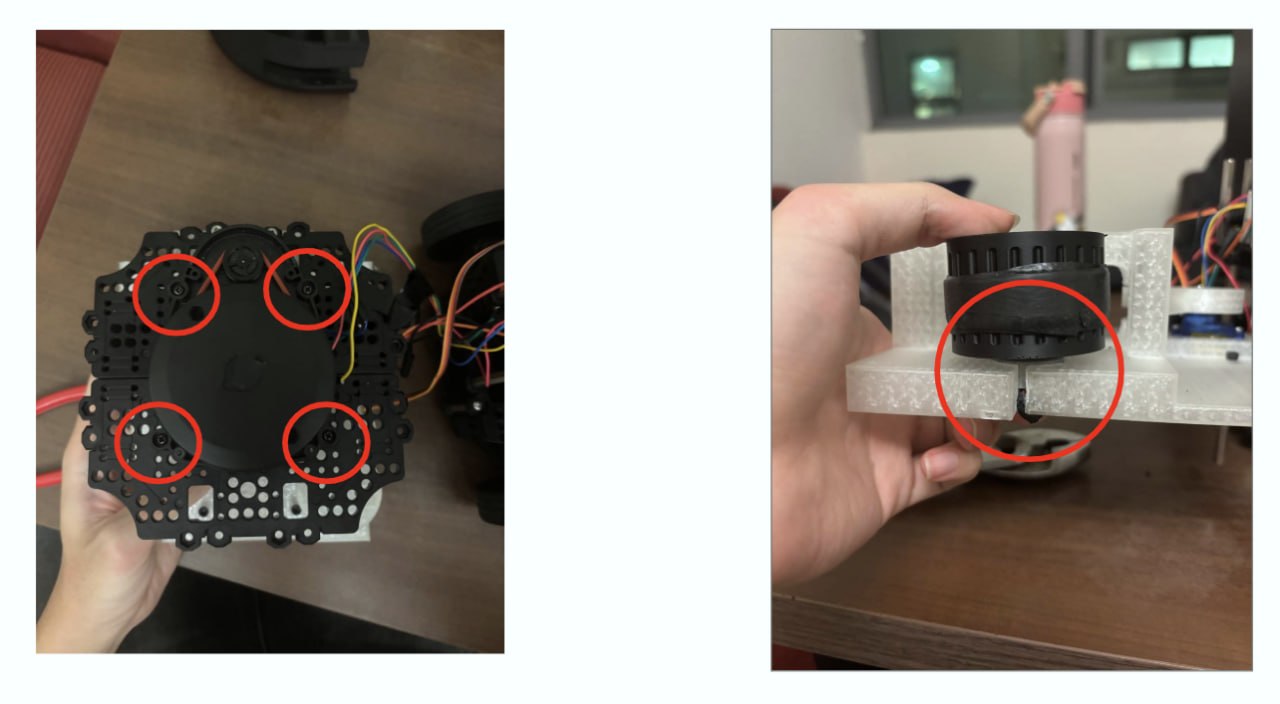
Iteration 4: Stability Improvement
- Design: We extended the rear of the 3D-printed flywheel housing so that it sits flush against the TurtleBot’s rear hex supports, allowing the housing to be directly bolted and tightened to the chassis.
- Result: This structural anchoring eliminated the vibrations caused by the rotational inertia of the spinning LiDAR. The robot’s overall steadiness was restored, providing a rigid base for the launching mechanism and ensuring consistent docking and firing operations.
|
Before Vibration issues due to lack of support |
After Rigid anchoring to hex supports |
5. Kinematics & Launch Requirements
The flywheel system was engineered based on the exact physics required to cross the docking gap.
- Launcher Exit Height: 151.0 mm
- Receptacle Height: 149.5 mm
- Vertical Drop ($\Delta y$): 1.5 mm
- Target Horizontal Range ($d$): 15 cm to 25 cm
Assuming a perfectly horizontal launch, the time of flight ($t$) before the ball drops 1.5 mm is calculated using gravity ($g = 9.81 \text{ m/s}^2$): $t = \sqrt{\frac{2\Delta y}{g}} \approx 0.0175 \text{ s}$
To cross the docking gap within this short time frame, the required horizontal velocity ($v_x = \frac{d}{t}$) is:
- For 15 cm range: $\approx 8.6 \text{ m/s}$
- For 25 cm range: $\approx 14.3 \text{ m/s}$
The dual DC motors and flywheel diameters were chosen and tuned specifically to impart an exit velocity within this 8.6 m/s to 14.3 m/s window.
6. Hardware & Components
TurtleBot3 Base Components
- First Floor Assembly — Base plate with Dynamixel motor mounts and ball caster.
- Connected Plates — Intermediate plate assemblies providing structural rigidity and component mounting.
- Fourth Floor Assembly — Top plate for LiDAR mounting.
- Ball Caster Assembly — Rear support with steel ball (3/8 inch) and caster cover.
- LiDAR Assembly — LDS-02 LiDAR sensor mount.
- Fasteners — M3 nuts, M2.5×12 and M3×6 pan head screws, hex standoffs (M3×35 and M3×45 FF), M3 threaded inserts, and inter-board brackets.
Custom Mechanical Components
| Component | File | Purpose |
|---|---|---|
| 50 mm Flywheel | 50 mm flywheel.SLDPRT |
Flywheel disc mounted on each RF300 motor shaft for ball acceleration |
| Ball Storage | Ball Storage.SLDPRT |
Curved gravity-feed tube holding up to 9 ping pong balls; designed to not obstruct LiDAR 360° FOV |
| Barrel Guide | Barrel Guide.SLDPRT |
Directs ball trajectory through the dual counter-rotating flywheel gap |
| Feeder Roller | Feeder Roller.SLDPRT |
Feeds balls from the storage tube into the barrel guide |
| SG90 Servo Mount | SG90 - Micro Servo 9g - Tower Pro.5-1.SLDPRT |
Mounting bracket for the servo gate actuator |
Custom Bill of Materials (BOM)
- 1x SG90 Servo Motor (for feeder gate)
- 2x RF300FA-12350 DC Motors (for dual flywheels)
- 1x L298N Motor Driver
- Standard M4 Bolts, Nuts, and Threaded Inserts
- BambuLab PLA Filament (1kg)
Ball Feed Path
- Storage: 9 ping pong balls sit in a curved gravity-feed tube.
- Gate: The SG90 servo actuates a gate that releases one ball at a time into the feed path.
- Feeder Roller: Guides the ball from the gate into the barrel guide.
- Barrel Guide: Channels the ball between the two counter-rotating flywheels.
- Launch: The ball exits through the flywheel gap with the desired velocity.
Motor Configuration
| Parameter | Value |
|---|---|
| Motor Model | RF300 Series (PEL00882) DC Motor |
| Quantity | 2 (counter-rotating) |
| Operating Voltage | 5V (via L298N motor driver) |
| Output Power | 0.05–0.50W per motor |
| RPM Range | 2,100–14,350 RPM (variable via PWM) |
| Control | Raspberry Pi GPIO → L298N (IN_HIGH/IN_LOW for direction) |
Servo Gate Configuration
| Parameter | Value |
|---|---|
| Model | SG90 Micro Servo 9g (Tower Pro) |
| Operating Voltage | 5V (from RPi 5V rail) |
| Control Signal | PWM from Raspberry Pi GPIO |
| Actuation Speed | ≤ 0.12 s/60° |
| Purpose | Gate control for single-ball release |
7. Assembly Instructions
Step 1: Preparation
- Insert Threads: Heat-press threaded inserts into the designated holes on the flywheel housing and ball storage components.
- Attach Flywheels: Firmly press-fit the two 3D-printed flywheels onto the shafts of the DC motors. Ensure they are fully seated to prevent wobble.
- Disassemble TurtleBot Layer: Remove the top waffle plate (Layer 4) of the TurtleBot, carefully disconnecting the LiDAR module.
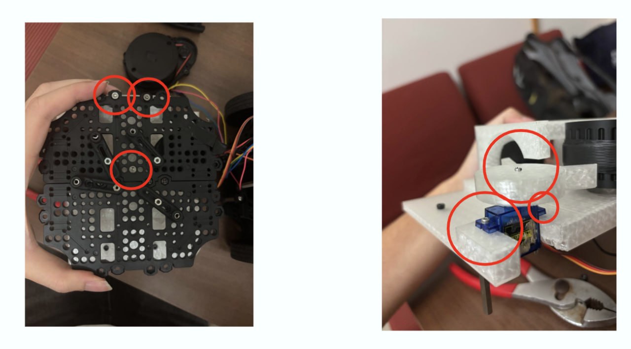
Step 2: Assembling the Launcher
- Mount Servo Assembly: Fasten the SG90 servo motor (with the attached feeder arm) onto its mounting bracket on the flywheel housing.
- Install Flywheel Motors: Press-fit both DC motors into the flywheel housing, ensuring the flywheels sit precisely alongside the shooting tube walls.
- Mount Feeder Roller: Securely attach the custom 3D-printed feeder roller to the spline of the SG90 servo motor.
| Fitting Motors & Servo | Installing Ball Storage |
|---|---|
 |
 |
Step 3: Integration with TurtleBot
- Position Launcher: Place the assembled launcher module between the hex supports and the Layer 4 waffle plate.
- Secure Mounts: Fasten the top and rear of the flywheel housing to the waffle plate and hex supports using M4 bolts and the threaded inserts.
- Install Storage Module: Mount the compact internal ball storage directly above the launcher intake.
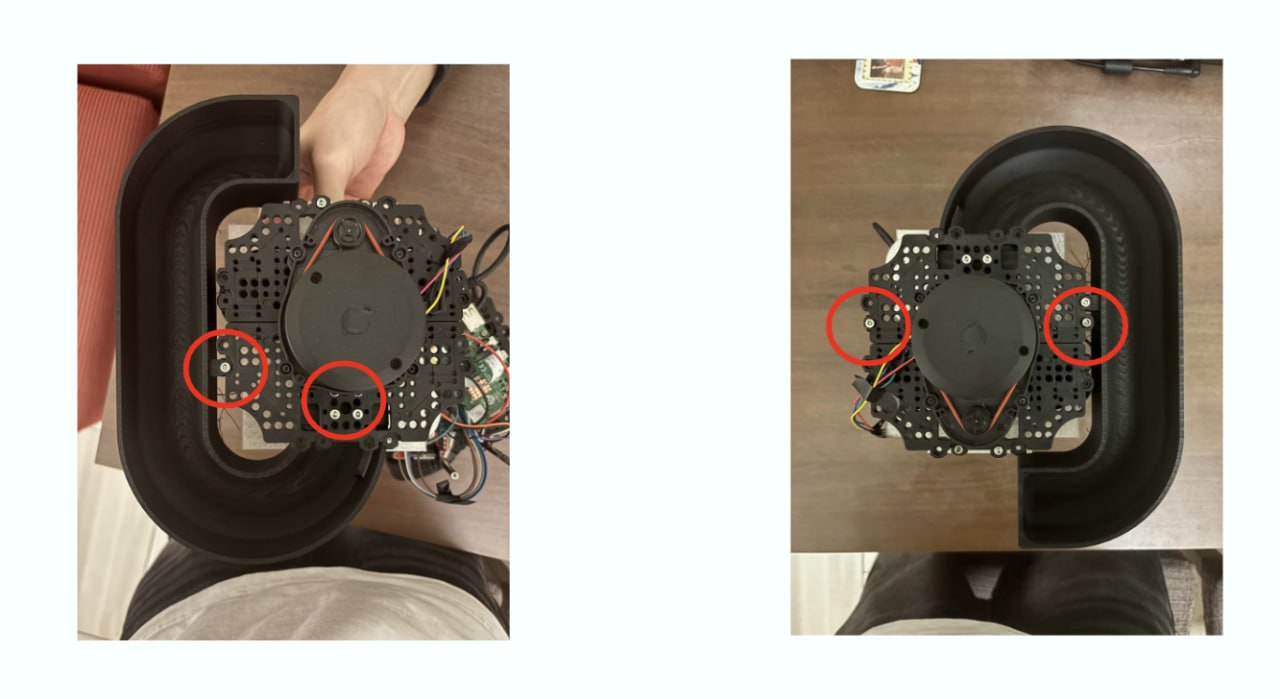
- Extend Supports: Install additional 60 mm hex supports to the left and right sides of the chassis to accommodate the new hardware height.
- Finalize Assembly: Reattach the Layer 4 waffle plate onto the extended hex supports, ensuring the LiDAR sensor remains in its stock configuration on top.
8. Assembly Best Practices & Troubleshooting
- Wiring & Routing: Install the L298N motor driver, route the DC motor power cables, and manage the servo wiring before fully bolting down the launcher housing. Doing this after assembly is extremely difficult.
- Dual Flywheel Tuning: Both flywheels must spin at the exact same RPM. If one motor receives slightly more power than the other, the ball will curve out of the launcher (similar to a curveball in baseball). Use the L298N motor driver’s PWM outputs to fine-tune and match the speeds.
- Flywheel Alignment: Ensure both flywheels are perfectly parallel to the shooting tube. Angular misalignment will introduce friction and cause inconsistent shots.
- Servo Zeroing: Before screwing the rotating arm onto the servo, write a quick test script to set the servo to its “neutral” (blocking) position. Mount the arm so it correctly blocks the ball in this state.
- Clearances: Double-check that no wires or custom parts are clipping into the LiDAR’s rotational path.