🔗 Navigation
Interface Control Documents
1. Hardware Interfaces
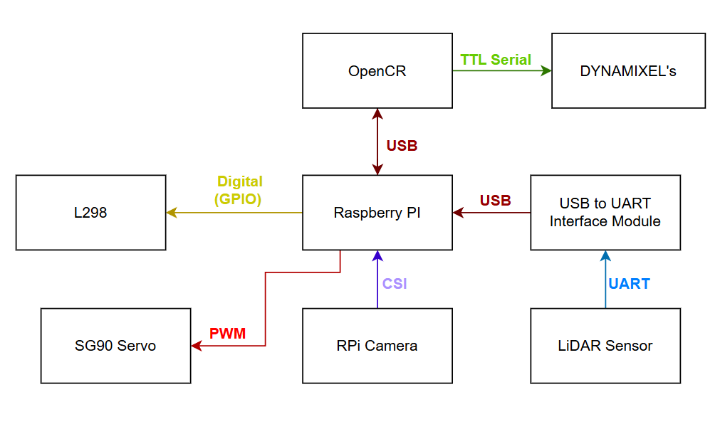 Communication protocols between all components (USB, UART, CSI, PWM, GPIO).
1.1 Communication Protocol Summary
| Interface |
Protocol |
Source |
Destination |
Data |
| USB |
USB 2.0 |
OpenCR 1.0 |
Raspberry Pi |
ROS 2 motor commands, IMU data, encoder feedback |
| USB (via adapter) |
UART → USB |
LDS-02 LiDAR |
Raspberry Pi |
360° laser scan data (LaserScan messages) |
| CSI |
Camera Serial Interface |
RPi Camera V2 |
Raspberry Pi |
Video frames (640×480 @ 30 FPS) |
| PWM |
GPIO PWM |
Raspberry Pi |
SG90 Servo |
Servo position commands (ball gate control) |
| GPIO Digital |
GPIO Output |
Raspberry Pi |
L298N Motor Driver |
Motor direction signals (IN_HIGH, IN_LOW) |
| GPIO PWM |
GPIO PWM |
Raspberry Pi |
L298N Motor Driver |
Motor speed signals (ENA, ENB) |
| TTL Serial |
Half-duplex TTL |
OpenCR 1.0 |
Dynamixel XL430 (×2) |
Motor position, velocity, and torque commands |
1.2 Power Interfaces
| Interface |
Voltage |
Source |
Destination |
Notes |
| Battery → OpenCR |
11.1V DC |
LiPo Battery (1800mAh) |
OpenCR 1.0 |
Direct connection |
| OpenCR → RPi |
5V DC (regulated) |
OpenCR 1.0 |
Raspberry Pi 4B |
Via OpenCR’s onboard regulator |
| OpenCR → Dynamixels |
11.1V DC |
OpenCR 1.0 |
Dynamixel XL430 (×2) |
Via Dynamixel daisy-chain |
| RPi → L298N |
5V DC |
RPi 5V GPIO rail |
L298N Motor Driver |
Powers flywheel motors at 5V |
| RPi → SG90 |
5V DC |
RPi 5V GPIO rail |
SG90 Servo |
Servo power supply |
| RPi → Camera |
3.3V DC |
RPi 3.3V rail |
RPi Camera V2 |
Camera power via CSI connector |
| RPi → LiDAR |
5V DC |
RPi 5V GPIO rail |
LDS-02 LiDAR |
Via USB-to-UART module |
1.3 GPIO Pin Mapping
| GPIO Pin |
Function |
Signal Type |
Connected To |
| GPIO 23 |
Motor A Forward |
Digital Output |
L298N IN1 |
| GPIO 24 |
Motor A Backward |
Digital Output |
L298N IN2 |
| GPIO 13 |
Motor A Enable |
PWM Output |
L298N ENA |
| GPIO 22 |
Motor B Forward |
Digital Output |
L298N IN3 |
| GPIO 27 |
Motor B Backward |
Digital Output |
L298N IN4 |
| GPIO 12 |
Motor B Enable |
PWM Output |
L298N ENB |
| GPIO (PWM) |
Servo Control |
PWM Output |
SG90 Signal Wire |
1.4 Grounding
A common ground (GND) is maintained across all components to ensure stable PWM and signal referencing. All ground rails (RPi GND, OpenCR GND, L298N GND, servo GND, motor GND) are tied together.
2. Software Interfaces (ROS 2)
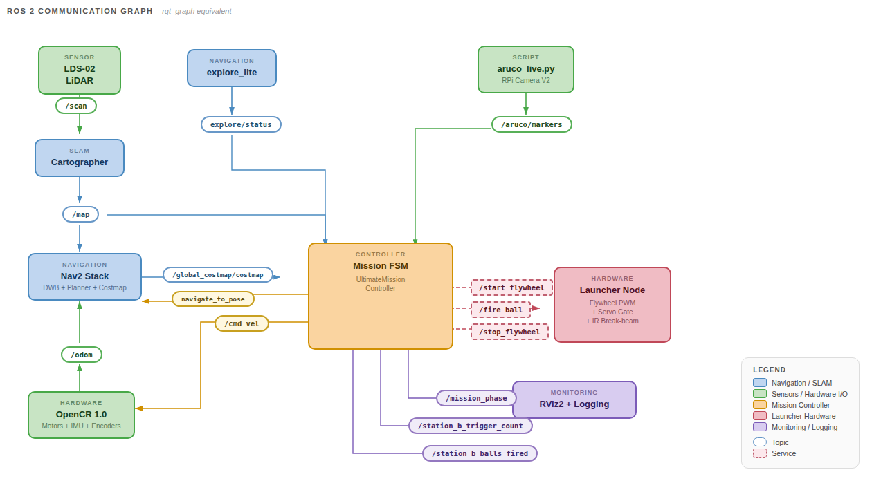 RQT graph showing the ROS 2 node communication topology.
2.1 ROS 2 Topics
| Topic |
Message Type |
Publisher |
Subscriber(s) |
QoS |
Description |
/scan |
sensor_msgs/LaserScan |
LiDAR driver |
Cartographer, Nav2 costmaps |
Best Effort |
360° laser range data |
/map |
nav_msgs/OccupancyGrid |
Cartographer |
Nav2, Mission Controller |
Reliable, Transient Local |
Occupancy grid (0.05 m/cell) |
/odom |
nav_msgs/Odometry |
OpenCR (via ROS bridge) |
Cartographer, Nav2 |
Best Effort |
Wheel encoder odometry |
/imu |
sensor_msgs/Imu |
OpenCR (via ROS bridge) |
Cartographer |
Best Effort |
IMU orientation and acceleration |
/cmd_vel |
geometry_msgs/Twist |
Nav2 / Mission Controller |
OpenCR motor driver |
Reliable |
Velocity commands (linear + angular) |
/aruco/markers |
visualization_msgs/MarkerArray |
aruco_live.py |
Mission Controller |
Best Effort, Volatile (depth 10) |
Detected ArUco marker poses in camera frame |
/mission_phase |
std_msgs/String |
Mission Controller |
Mission GUI, logging |
Reliable |
Current mission phase name |
/explore/status |
— |
explore_lite |
Mission Controller |
— |
Exploration completion status |
2.2 ROS 2 Services
| Service |
Service Type |
Server |
Client |
Description |
/start_flywheel |
std_srvs/Trigger |
ball_launcher.py (RPi) |
Mission Controller |
Spin up both flywheel motors at full speed |
/fire_ball |
std_srvs/Trigger |
ball_launcher.py (RPi) |
Mission Controller |
Trigger servo to release one ball |
/stop_flywheel |
std_srvs/Trigger |
ball_launcher.py (RPi) |
Mission Controller |
Stop both flywheel motors |
Service call protocol: The mission controller calls each service asynchronously via call_async() and polls for completion. A 5-second timeout is applied to wait_for_service() before each call.
2.3 ROS 2 Actions
| Action |
Action Type |
Server |
Client |
Description |
/navigate_to_pose |
nav2_msgs/NavigateToPose |
Nav2 BT Navigator |
Mission Controller (via BasicNavigator) |
Goal-directed navigation with obstacle avoidance |
The mission controller uses nav2_simple_commander.BasicNavigator to send goal poses and monitor navigation progress. Goals can be cancelled immediately if markers are found mid-transit.
| Parent Frame |
Child Frame |
Source |
Description |
map |
odom |
Cartographer |
SLAM-corrected map-to-odometry transform |
odom |
base_link |
OpenCR (wheel encoders) |
Odometry-based robot pose |
base_link |
base_footprint |
Static TF |
Ground-plane projection of robot base |
camera |
(marker frames) |
aruco_live.py |
ArUco marker poses in camera frame (converted to map frame by mission controller) |
The mission controller performs camera-to-map coordinate conversion by looking up the map → base_link transform and applying a 4 cm lateral camera offset.
3. Inter-Subsystem Data Flows
3.1 Exploration Data Flow
LiDAR → /scan → Cartographer → /map → Nav2 Global Costmap → NavFn Planner → /cmd_vel → OpenCR → Motors
                                  ↓
                          explore_lite (frontiers)
                                  ↓
                        Mission Controller (goal selection)
                                  ↓
                        Nav2 Action Server (/navigate_to_pose)
3.2 Marker Detection Data Flow
RPi Camera V2 → aruco_live.py (cv2.aruco detection + cv2.solvePnP)
      ↓
/aruco/markers (MarkerArray, camera frame)
      ↓
Mission Controller: marker_cb()
      ↓
Quality Gates: |cam_x| < 0.15m, 0.15m < cam_z < 2.0m, valid TF
      ↓
camera_to_map(): TF lookup (map → base_link) + camera offset projection
      ↓
detected_markers dict: {marker_id: (map_x, map_y, normal_yaw)}
      ↓
YAML persistence: /tmp/aruco_dock_poses.yaml
3.3 Docking Data Flow
Stage 1: YAML stored pose → compute standoff point (0.6m) → Nav2 goal
      ↓
Stage 2: Live marker sighting → update pose → Nav2 goal (0.35m)
      ↓
Stage 3: Real-time /aruco/markers → proportional cmd_vel control
         Align (angular only) → Drive (linear + angular) → Dead-reckon (blind zone)
3.4 Launcher Data Flow
Mission Controller (docking confirmed)
      ↓
/start_flywheel (Trigger service) → ball_launcher.py → GPIO → L298N → RF300 motors
      ↓
[Station A: timed delays] or [Station B: trigger marker detection]
      ↓
/fire_ball (Trigger service) → ball_launcher.py → GPIO → SG90 servo
      ↓
/stop_flywheel (Trigger service) → ball_launcher.py → GPIO → L298N stop
4. ArUco Marker Interface
4.1 Marker ID Assignments
| ID |
Purpose |
Location |
| 0 |
Station A dock marker |
Fixed on Station A receptacle |
| 1 |
Station B dock marker |
Fixed on Station B rail assembly |
| 2 |
Station B trigger marker |
Inside the moving receptacle hole |
4.2 Marker Detection Parameters
| Parameter |
Value |
| Dictionary |
DICT_6X6_250 |
| Physical Marker Size |
5 cm (0.05 m) |
| Detection Resolution |
640 × 480 |
| Frame Rate |
30 FPS |
| Pose Solver |
cv2.solvePnP with SOLVEPNP_IPPE_SQUARE |
| Calibration |
Camera intrinsic matrix (K) and distortion coefficients from .npz file |
4.3 Quality Gate Thresholds
| Gate |
Condition |
Purpose |
| Lateral offset |
|cam_x| < 0.15 m |
Reject oblique sightings with poor pose accuracy |
| Depth range |
0.15 m < cam_z < 2.0 m |
Reject out-of-focus or low-resolution readings |
| TF availability |
Valid map → base_link transform |
Required for map-frame coordinate conversion |
5. Launch File Interface
The bringup_all.launch.py file orchestrates system startup using event-driven triggers:
| Step |
Trigger |
Process Started |
| 1 |
Immediate |
Cartographer (SLAM) |
| 2 |
Cartographer stdout contains "Trying to create a map of size" |
Nav2 navigation stack |
| 3 |
Nav2 stdout contains "Creating bond timer" |
Mission FSM Node (UltimateMissionController) |
The aruco_live.py camera detection script is launched separately on the RPi via SSH, independent of the main launch file. The ball_launcher.py hardware controller is also run separately on the RPi.